Setup
Step by Step Instructions
Using the MPLAB® Code Configurator (MCC), this project creates an analog input to read a potentiometer and control an LED from a digital output. When the potentiometer is turned right of the center position, the LED will light up. When the potentiometer is turned left of the center position, the LED will be off.

The project uses:
- PIC16F18875
- HPC Curiosity Board
- MPLAB X IDE
- MPLAB Code Configurator (MCC) plug-in
- MPLAB XC8 Compiler
To follow along with these steps, MPLAB X IDE should be open and the HPC Curiosity Board connected to the computer through a USB cable.
Step 1 - Create a new standalone project in MPLAB X for a PIC16F18875.
If this is your first time creating an MPLAB X project, please visit the "Create a Standalone Project" page to follow step-by-step instructions on how to do this.
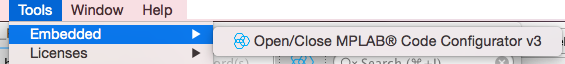
Step 2 - Open MCC under the Tools > Embedded menu of MPLAB X IDE.
Step 3 - Select the peripherals for your project.
In this project, these peripherals will need to be selected:
- System Module
- Interrupt Module
- Pin Module
- ADCC (Foundation Services …)
The System Module, Interrupt Module, and Pin Module will be automatically included, but the ADC must be selected for the project. The list of peripherals will show up under the Device Resources list. Double-click on the ADC to have it added to the project. The result should look like the picture below.
