Setup
Step by Step Instructions
Using the MPLAB® Code Configurator (MCC) simplifies the setup for the various registers within the device to create a digital input. To demonstrate how to get started, this project monitors a momentary switch connected to pin RB4 that is enabled as a digital input using an internal pull-up. The code will light an LED connected to RA4, enabled as a digital output when the switch is pressed.

The project uses:
- PIC16F18875
- HPC Curiosity Board
- MPLAB X IDE
- MPLAB Code Configurator (MCC) plug-in
- MPLAB XC8 Compiler
To follow along with these steps, MPLAB X IDE should be open and the HPC Curiosity Board connected to the computer through a USB cable.
Step 1 - Create a new standalone project in MPLAB X for a PIC16F18875.
If this is your first time creating an MPLAB X project, please visit the "Create a Standalone Project" page to follow a step-by-step instruction on how to do this.
Step 2 - Open MCC under the Tools > Embedded menu of MPLAB X IDE.

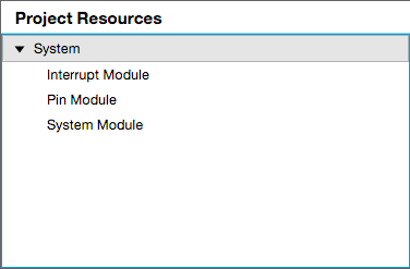
Step 3 - Select the peripherals for your project. For this project, the following peripherals need to be selected:
- System Module
- Interrupt Module
- Pin Module
The System Module, Interrupt Module, and the Pin Module will all be automatically included when you launch the MCC. The result should look like the picture below: