Oscillator Overview
Clocking
At the heart of the PIC MCU is the oscillator module. The oscillator is the heartbeat or system clock source that makes the device run. The oscillator module has a wide variety of clock sources and selection features that allow it to be used in many applications while maximizing performance and minimizing power consumption.
Clock sources can be supplied from external oscillators, quartz crystal resonators, ceramic resonators, and Resistor-Capacitor (RC) circuits. In addition, the system clock source can be supplied from one of two internal oscillators.
The oscillator module can be configured in one of the following clock modes:
- ECL:External Clock Low-Power mode (0 MHz to 0.5 MHz)
- ECM: External Clock Medium-Power mode (0.5 MHz to 4 MHz)
- ECH: External Clock High-Power mode (4 MHz to 32 MHz)
- LP: 32 kHz Low-Power Crystal mode
- XT: Medium Gain Crystal or Ceramic Resonator Oscillator mode (up to 4 MHz)
- HS: High Gain Crystal or Ceramic Resonator mode (4 MHz to 20 MHz)
- EXTRC: External Resistor-Capacitor
- INTOSC: Internal Oscillator (31 kHz to 32 MHz)
Clock Source modes are selected by the FOSC<2:0> bits in a Configuration Word. The FOSC bits determine the type of oscillator that will be used when the device is first powered.
The ECH, ECM, and ECL clock modes rely on an external logic level signal as the device clock source.
The LP, XT, and HS clock modes require an external crystal or resonator to be connected to the device. Each mode is optimized for a different frequency range.
The EXTRC clock mode requires an external resistor and capacitor to set the oscillator frequency.
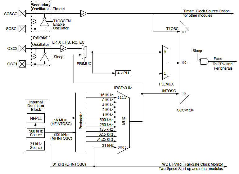
The INTOSC internal oscillator block produces low, medium, and high-frequency clock sources, designated LFINTOSC, MFINTOSC, and HFINTOSC. A wide selection of device clock frequencies may be derived from these three clock sources.
A block diagram showing a typical Oscillator Module structure is below (captured from PIC16F1713):