Analog vs Digital Configuration
Depending upon which Enhanced Mid-Range PIC MCU is used, up to 30 digital pins can be configured to be analog pins. The ANSELx registers are used to configure the mode of the analog capable pins. (ANSELA controls the mode of all the analog capable pins on PORTA, ANSELB controls the mode for PORTB, ANSELD for PORTD, etc.).
The analog capable pins in the port are mapped to individual bits in an ANSELx register. A value of '1' in a bit of an ANSELx register will enable the analog mode of the corresponding port pin. A value of '0' configures the pin to be digital.
At RESET all the analog capable pins revert to analog mode. The MCU sets all the relevant ANSELx bits to '1'.
Example:
Pin 24, in Figure 4 on the previous page, can either be configured as Analog Channel 9 or as digital pin RB3.
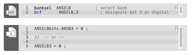
To use this pin as a digital pin, bit 3 of ANSELB must be cleared.
When working with analog-capable digital pins remember:
- If an ADC conversion is attempted on an analog capable configured as digital, the conversion will return an unchanging value which is not reflective of the voltage on the pin.
- If a pin is configured as an analog pin, any digital value read from the pin will always be '1' regardless of the voltage on the input pad.
- If an analog configured pin is written to as if it were a digital pin, the pin output level will not change.