Basic I/O Structure
Digital Inputs and Outputs
Almost every pin on the Enhanced Mid-Range PIC Microcontroller (MCU) can be used as a digital input or output pin. Digital pins share these attributes:
- Ability to monitor digital inputs
- Control digital output signals
- Internal weak pull-ups
- Multiplexed with peripherals
- High drive capability (up to 25 mA sink/source on many I/O pins)
- Direct single-cycle bit manipulation
- 4 kV ESD protection diodes
At RESET:
- Digital pins revert to input (Hi-Z)
- Analog-capable pins revert to analog
Digital I/Os are controlled by software in the MCU. The MCU program configures, reads, and outputs the values to digital pianos.
I/O Ports

Figure 1. I/O Port
Individual Digital I/O pins are combined into groups called ports. I/O ports contain up to 8 digital pins. Digital I/O pins can be accessed individually on a pin-by-pin basis. All the members of a particular I/O port can also be accessed in one instruction cycle by one of the MCU's byte-access instructions.
I/O ports are referred to by letter (i.e. PORTA, PORTB, PORTC, ... ) The number of I/O ports will vary depending on the PIC MCU being used. Consult the individual data sheet to determine the PORT assignments for a PIC MCU.
Typical Digital I/O Pin

Figure 2. Digital Pin I/O
Five registers are available to configure and control a digital I/O pin:
- TRISx: Sets the direction as either input or output.
- ANSELx: Determines if an analog capable pin works as an analog input or digital I/O.
- LATx: Used to output values for a digital pin.
- PORTx: Reads the input value of a digital pin.
- WPUx: Enables the internal weak pull up.
There are five I/O control registers for each port.
- For port A the control registers are TRISA, ANSELA, LATA, PORTA, and WPUA.
- For port B the control registers are TRISB, ANSELB, LATB, PORTB, and WPUB.
Identifying the I/O Pins on the Datasheet
Digital I/Os can share pins with other peripherals and MCU control lines. Some digital I/O pins are Analog Capable and can be configured to operate as analog input pins. Consult the pin diagram of the device data sheet to determine which pins are available as digital I/O.
Digital pins are identified by three sequential identifiers:
- The first identifier for a digital pin is the letter R.
- The second identifier is a letter of the PORT which the pin is associated (such as A for PORTA, B for PORTB, etc.).
- The final identifier is a number from 0 - 7 indicating the position in the PORT held by the Pin.

Figure 3. All the digital pins associated with PORTB are highlighted in Yellow
Note: PORTB members range from RB0 - RB7.
For the other pins on the MCU:
- Analog capable pins are designated with the two letters AN followed by a number.
- MCU Peripheral and Control pins are designated by name on the datasheet.
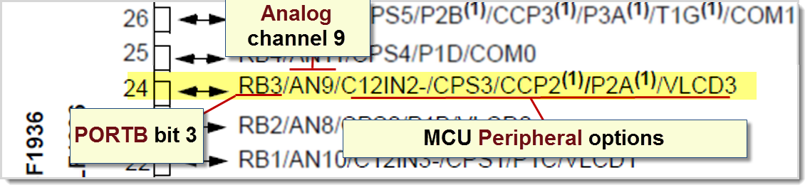
Figure 4. In the close-up of the RB3/pin 24, the options for the PIC16L/F1936 are shown
Note: Pin 24 can be configured as digital Pin PORTB bit 3, analog channel 9, or one of several peripherals
In order for a pin to operate as a digital pin, all peripherals associated with the pin must NOT be enabled.
If an analog capable pin is to be used as a digital pin, in addition to not enabling the peripheral, the pin must be specifically configured as a digital pin.