Comparators with Hysteresis (Schmitt Trigger)
Noise in the real-world systems can cause fluctuations in signal levels, hence, the need for implementing hysteresis. The figure below shows a possible scenario that the changes in input levels cause a false trigger of the comparator outputs.

Hysteresis is simply a positive feedback technique used in, for example, op-amp configurations to provide pre-determined comparator thresholds. Hysteresis can also be called a Schmitt Trigger. The figure below shows an op-amp hysteresis circuit. This op-amp is an inverting comparator with VIN connecting to V– (inverting input) while the positive terminal (V+) connects to the midpoint of the voltage divider (R2 and R3) forming a positive feedback network. V+ is now the upper and lower thresholds of the comparator set by the R2 and R3.
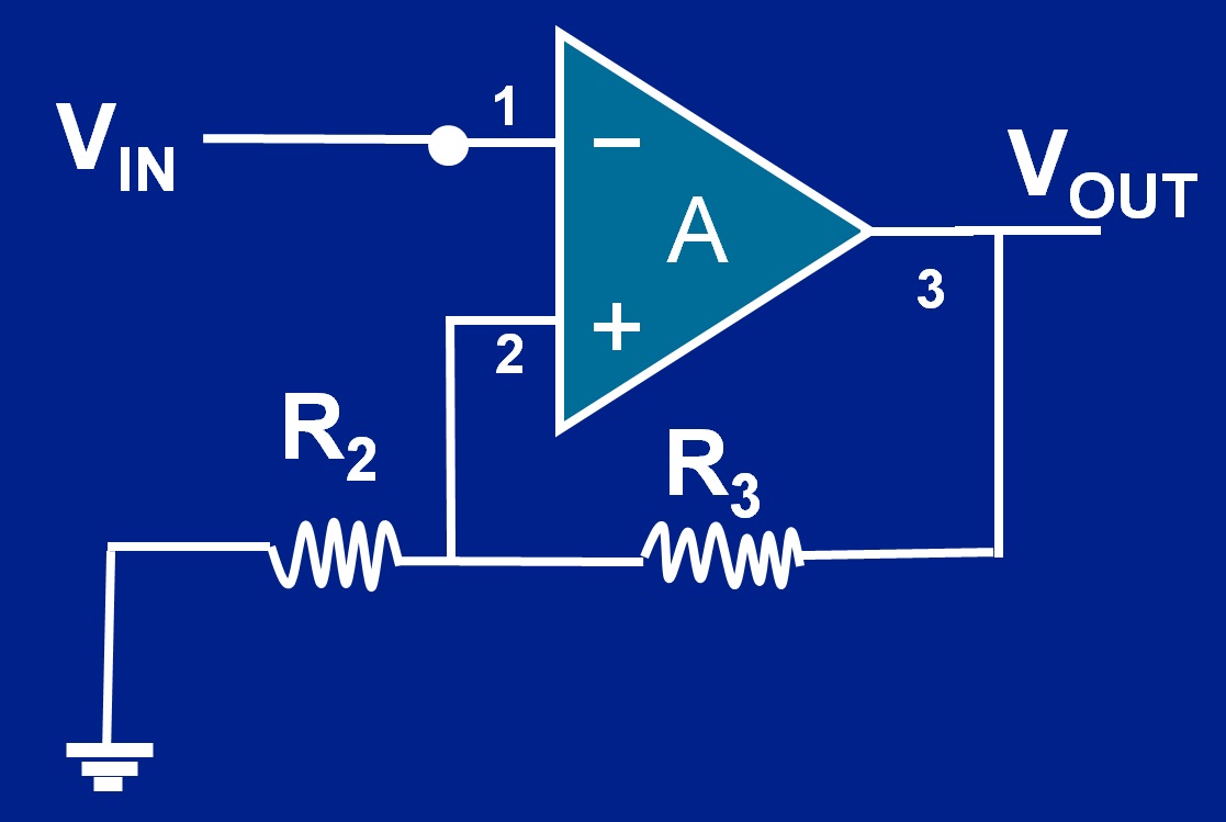
Assuming VDD and VSS of the op-amp are +5V, and -5V, and R2 = R3. When VIN starts to rise from 0V, VOUT goes to the positive rail 5V due to its high gain. The upper threshold is now at 2.5 V set by the voltage divider. While VIN continues to rise from 0V (before 2.5 V), VOUT stays at 5 V due to the high gain of the comparator. Once VIN rises slightly above 2.5 V, VOUT flips to the – 5 V rail (V– > V+). The comparator’s threshold V+ now is set at – 2.5 V, again by the voltage divider. VIN continues to increase above 2.5 V while VOUT remains at – 5 V (V– > V+). As VIN (V–) starts to fall from its peak just below 2.5 V, it continues to stay low -5V. V– remains less than V+. Once VIN (V–) falls below – 2.5 V (V– < V+), VOUT flips to the positive rail, +5V. The same mechanism repeats to the next cycle. We now successfully set a hysteresis zone between +2.5 V and -2.5V. To change the zone threshold values, you can simply adjust the size of R2 and R3.
