Programming the Design Into the Device
This step will run FlashPro in batch mode to program the PolarFire MPF300TS on the PolarFire Splash Kit board shown below.
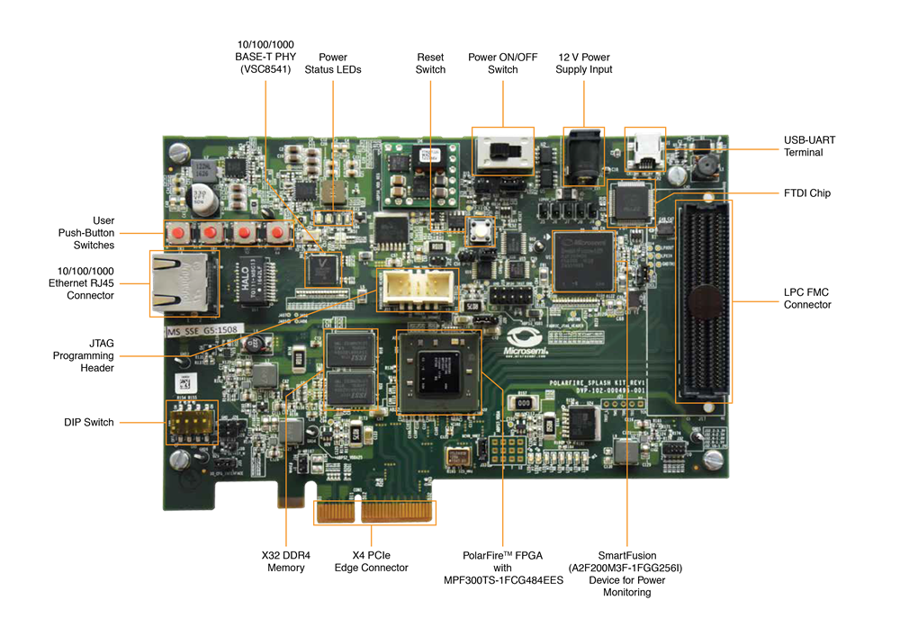
1) Prior to programming (and powering up) the PolarFire Splash Kit board, confirm that the jumpers are positioned as shown in the table below.
| Jumper | Location | Function | Setting |
|---|---|---|---|
| J5, J6, J7, J8, J9 | Top edge of the board near the 12V power supply input. | Jumpers to select the PolarFire JTAG or A2F JTAG. Pin 1–2 programming the power sequence and monitoring chip through the FTDI. Pin 2–3 for programming the PolarFire FPGA through FTDI | 2-3 installed (programming through FTDI) |
| J11 | Near the reset switch (SW2). | Jumper to select the external JTAG or the on-board FTDI chip for programming the PolarFire device. Pin 1–2 for programming through the FTDI chip | 1-2 installed |
| J10 | Near the reset switch (SW2). | Jumper to select programming through external SPI flash | Open |
| J3 | Near the Power On/Off switch. | Jumper to select the core voltage. Pin 1–2 installed for 1.05 V. Pin 1-2 open for 1.0 V | Open |
| J4 | Right of the AC jack (J9). | Jumper to select the SW3 input or the ENABLE_FT4 232 signal from the FT4232H chip. Pin 1-2 for manual power switching using SW3. Pin 2-3 for remote power switching using the GPIO capability of the FT4232 chip | 1-2 installed |
| J32 | Lower right-hand corner of the board. | Jumper to select the PolarFire VCCIO voltage (VCCIO_HPC_VADJ) to 1.2V, 1.5V, 1.8V, 2.5V, or 3.3V. Pin 1-2: 3.3. Pin 3-4: 2.5 V. Pin 5-6: 1.8 V. Pin 7-8: 1.5 V. Pin 9-10: 1.2V | 1-2 installed |
2) Connect 12 V power supply brick to the J2 connector.
3) Connect a USB cable between the J1 mini USB connector and the host PC.
4) Slide the main power switch SW1 to ON position.
5) Install the FlashPro4 drivers if prompted. The drivers are located in the <Libero SoC PolarFire v2.2 Installation Directory>\drivers folder.
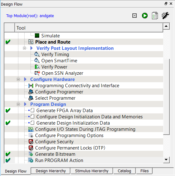
6) Expand Program Design in the Design Flow window. Right-click Run PROGRAM Action and select Run to generate the programming file and begin programming.
7) FlashPro runs in batch mode and programs the device. Programming messages are visible in the Libero SoC Log window (programmer number will differ).
Do not interrupt the programming sequence.
8) The following message should be visible in the Reports view under Run PROGRAM Action when the device is programmed successfully (programmer number will differ):
programmer 'E2001JZK2X' : device 'MPF300T_ES' : Executing action PROGRAM PASSED.
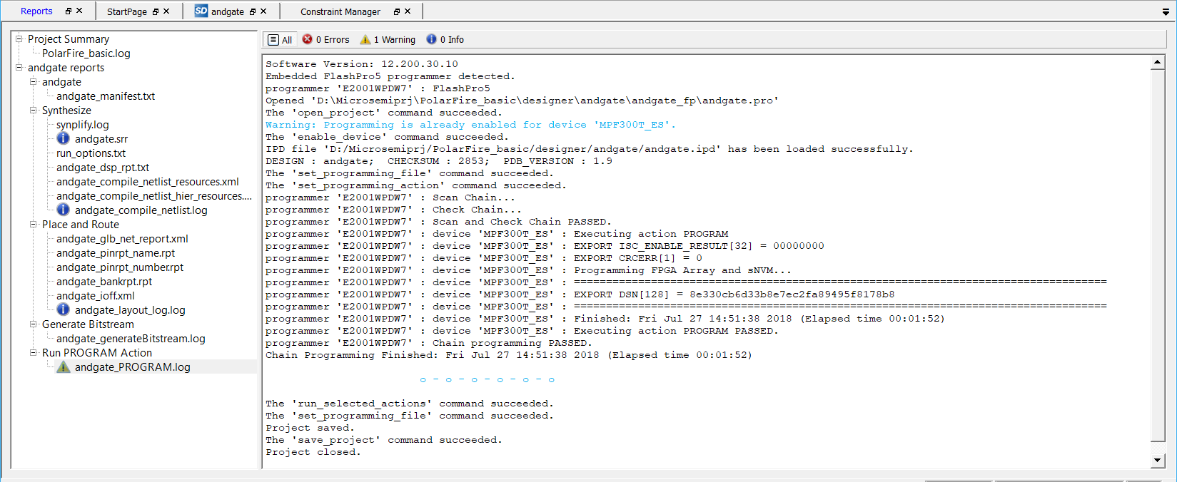
A green check mark will appear next to the Program Design and Run PROGRAM Action in the Design Flow window, to indicate programming completed successfully.
9) Click Project > Save from the Libero menu to save your completed project. Do not close it, we will use it again.