MCC Pin Module Setup
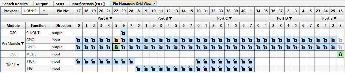
Open the Pin Manager: Grid View tab and then click on the GPIO Output pin row in the RA5 column to select the blue lock. It should turn green. This will enable the port digital output to the RA5 pin connected to the D3 LED. It should look like the picture when completed:
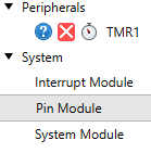
Now close the Pin Manager: Grid View. Click on the Pin Module under Project Resources.
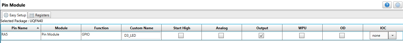
The center screen will show RA5 listed on the I/O chart. Change the Custom Name to something more descriptive like D3_LED. Click on the Output box to make the pin an output (if not checked) and make sure Analog and WPU are not checked (click on them to uncheck them).