Launching MCC & MCC Setup
Open MCC under the Tools > Embedded in the MPLAB X IDE menu.

Select the peripherals for your project. For this project, the following peripherals need to be selected:
- System Module
- Interrupt Module
- Pin Module
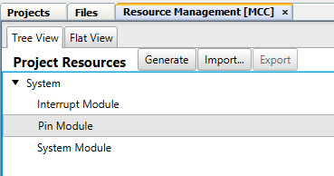
The System Module, Interrupt Module, and Pin Module will all be automatically included when you launch MCC.
Open the Pin Manager Grid View. Click on the PORTA - 4 blue lock symbol in the Output row. This will change it to locked and turn it green in color. Also, click on the PORTB - 4 blue lock symbol in the Input row to change it to green and locked. Check that the Reset is blue and unlocked. Click on it if it is set to green and locked. This adds the RA4 and RB4 I/O pins to the project.

Close the Pin Manager and then click on the Pin Module selection in the Project Resources section.

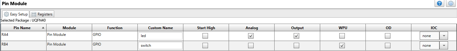
The center section should show RA4 and RB4 listed on the I/O chart.
- RB4 will be the input that will read the switch. The Weak Pull-Up (WPU) box is checked.
- RA4 will be the output and control the LED. Click on the Output box to make the pin an output.
Change the names of the pins to led for RA4 and switch for RB4.
These steps are shown in the "How to Setup the Pin Module" video: