MCC System Setup
Timer0 Example
The first step after launching the MCC within MPLAB® X is to select the peripherals we will use in this example to set up the System settings, Timer0 configuration, and the I/O setup.
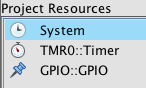
System Setup
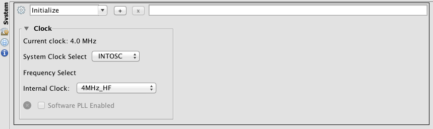
The System setup requires two sections to be configured - the oscillator and the configuration.
The first is the oscillator. A 4 MHz internal oscillator is selected and the Timer0 clock sources are the internal clock.
The configuration settings include the defaults. Also, the MCLR pin is set to be a digital I/O pin so the MCLR pull-up is internal to the PIC® MCU.
